Our system will evaluate the answer based on this AI-generated description.
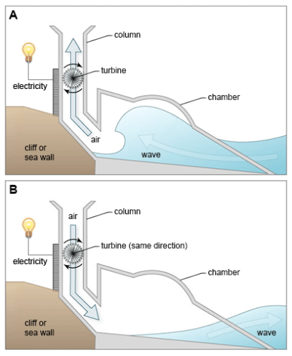
The image displays two diagrams, A and B, illustrating wave energy conversion methods using air to drive turbines for electricity generation. Both show waves approaching a cliff or sea wall, compressing air in a chamber which then turns a turbine connected to an electricity generator at the top. Diagram A depicts the turbine blades orientated to spin in one direction when air flows upwards due to a wave and depicts the absence of air movement with the receding wave. Diagram B shows a one-way air flow system where the turbine blades rotate in the same direction regardless of the wave's motion. Each diagram has three labels: "electricity," "turbine," and "cliff or sea wall," with additional labels "column" and "chamber" for the passages where air and water move, respectively. The diagrams use blue for water and shades of gray for the mechanical and structural components.
Given the complexity of the image, the above description may not be entirely accurate.
Skyrocket your IELTS band score by 1-2 points in under a month with our premium plan!
Note: Both the topic and the answer were created by one of our users.
The diagram demonstrates a system that is used for producing electric power via wave energy
Overall, the electricity is collected through turbines. In this diagram, the direction of air, changes wave’s way backwards and forwards, and this affects the amount of power.
Firstly, in A diagram, wave’s direction is on to top of the columns, at this time the wave which has entered chambers pushes the air to the out of turbine. in this stage this causes the movement of turbines, and electricity is being generating respectively.
Secondly, when wave leaves the chamber, due to the pressure of air has entered by columns, creating emptiness inside the chamber. While this happening, the turbines is still continuing generating electricity by spinning in the same direction.
Word Count: 124
